Click here to know aboutComputer Network

Now we start at the 1st layer which is known as PHYSICAL Layer.


OSI MODEL:
What is the OSI model?
The Open Systems Interconnection (OSI) model is a conceptual model created by the International Organization for Standardization
The OSI provides a standard for different computer systems to be able to communicate with each other.
The OSI model can be seen as a universal language for computer networking. It’s based on the concept of splitting up a communication system into seven abstract layers, each one stacked upon the last.

Why it's name Physical layer ? & Functionality
1.TheCommunication between the two or more devices by through the Physical medium just like as CABLE, WIRE etc; so it's name Physical Layer.
2.The data transmitted by the CABLES is in the form of SIGNAL,it may be DIGITAL or ANALOG SIGNAL. we will discuss about it in this session.
3.The next thing is the devices which is used to transmit the data with out any loss. The one and only device is the REPEATER which is used in Physical Layer to transmit the data.
4.Then we know about the the data TRANSMISSION MODE .
5.In this layer the multiplexer is used for multiplexing and demultiplexing and also MODULATOR is used for Modulation and demodulation. In this session we also know about the ENCODING which is used in Physical Layer. In this encoding part we see about the MANCHESTER ENCODING.
1_ CABLES & WIRE:
There are 3 Types of cable which is used for data transmission in Physical Layer, such as

(a) Unshielded Twisted Pair Cable (UTP):-
In this UTP there are two types of cable which is well-known for communication, such as- (10BaseT) & ( 100BaseT) Cable.
Here (10BaseT)_ represent that 10= 10mbps (ten mb per sec).
& Base represent that for _ Which Bandwidth i.e (BASE BAND) or (BROAD BAND).
& T represent that for distance i.e T = 100mtr.
(b) Co-axial CABLE:
There are also we use well known 2 types of cable such as (10Base2) &(10Base5)
But Here (10BaseT)_ represent that 10= 100mbps (100 mb per sec).
& Base represent that for _ Which Bandwidth i.e (BASE BAND) or (BROAD BAND).
& 2 represent for distance 200mtr and also 5 represent as 500mtr.
(c) Optical fibre:
Here we use 100Base_FX. FX represent that the distance FX=2km.
Physical Layer Devices:
There are two types of devices which is used in Physical Layer such as, . REPEATER & HUB.
REPEATER :
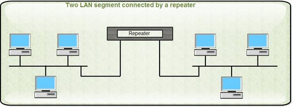
1. It is a 2 port Device
2. it regenerate the signal strength
3.& Forward the by through wire
4.No_FILTERING: i.e this device has no idea to send the data to which node. It just BROADCAST the data.
5.Collision Domain:_ Collision must be occurr. If one node send the data at that time the another device send data then collision is occurring. Here maximum Collision Domain=n. Wher n represent that number of nodes connected to the repeater.
HUB:

1. Multiport Devices.
2. Forwarding
3. No Filtering
4. Maximum Collision Domain should be occurr (n).
5. If the physical wire are cut in some cases, the repeater can't denotes it; but In HUB there are some light that blinking to show some kind of problem.
Discuss about some numerical question of Topology.
MESH TOPOLOGY:

*The cable are connected to each other nodes. So what is the Number of Cable in the MESH TOPOLOGY:- n(n-1)/2 where n represent the number of nodes.

* Reliability is high cause, incase if the connection should be lost due to any physical problems or any cutting of cable; then another path can be used.
*COST is almost high because large number of cables are used.
STAR TOPOLOGY:
*All the nodes & devices are connected to the HUB by through the Cable so what is the Number of Cable in the STAR TOPOLOGY:- n the where (n) represent as the number of nodes.
*Each device connected to the HUB so it contains one port.
Number of port for each devices is 1.
Total Number of port is (1*n)=n.
*Reliability is lowest because if the connection should be lost due to any physical problems or any cutting of cable; then another OPTION is not here.
BUS TOPOLOGY:
*In the BUS TOPOLOGY there are one cable which is known as Backbone or THICKNET & all the nodes are serially connected to the Cable for sharing the information. So Number of Cable in the BUS TOPOLOGY:_
BUS Number of nodes cable (n)+ thicknet1 which is =n+1.
*Each device connected to the THICKNET so it contains one port.
Number of port for each devices is 1.
Total Number of port is (1*n)=n.
*Reliability is lowest because if the connection should be lost due to any physical problems or any cutting of cable; then another OPTION is not here.
Comments
Post a Comment